
Design research on a smart infusion device to reduce medical workload and enhance patient safety

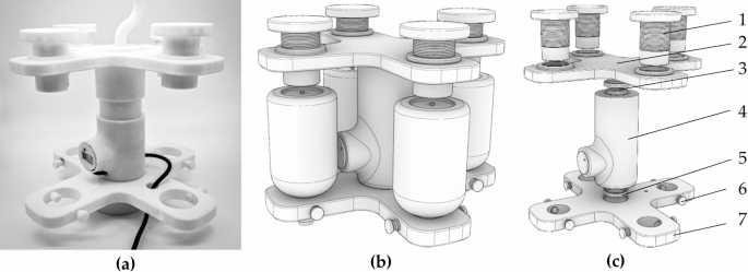
This section introduces the structure and functionality of the smart infusion automatic medication replacement device. Figure 1 illustrates the overall design and the relative positions of each component within the system. The fixed calibration mechanism, liquid level monitoring mechanism, and rotary replacement mechanism are located at the top of the assembly, while the plug-and-push mechanism and control module are situated at the bottom. These components work in concert to achieve smart monitoring of medication bottle levels and automated replacement. This chapter will focus on describing the operation of the mechanisms responsible for automatic bottle replacement and liquid level monitoring. Furthermore, it will detail the design of the core systems to highlight their role in enhancing the continuity and safety of infusion therapy.

Schematic of the smart infusion automatic medication replacement device: (a) actual photograph of the smart infusion automatic medication replacement device and (b) model diagram of the device. (1. fixed calibration mechanism, 2. liquid level monitoring mechanism, 3. rotary replacement mechanism, 4. plug-and-push mechanism, 5. control module, 6. device casing)
Enclosure design
The enclosure design of the smart infusion automatic medication replacement device is divided into two parts: the upper and lower sections, each serving distinct functions. The upper enclosure primarily protects and secures the liquid level monitoring mechanism and other upper components, shielding them from external environmental influences during operation. As shown in Fig. 2, the design of the lower enclosure is particularly critical, as it houses the rotary replacement mechanism, plug-and-push mechanism, and control module. The lower enclosure is meticulously arranged to ensure smooth operation, coordination, and efficiency among the components. The rotary replacement mechanism is centrally positioned within the lower enclosure to facilitate the automatic replacement of medication bottles. The plug-and-push mechanism is located adjacent to the rotary replacement mechanism, ensuring stability and precision during the bottle replacement process. The control module is situated on the side of the lower enclosure, allowing for easy wiring and transmission of control signals. The dimensions of the lower enclosure are 147 mm in length, 54.6 mm in width, and 186.08 mm in height.

Schematic of the smart infusion automatic medication replacement device enclosure dimensions and structure.
As depicted in Fig. 3, the enclosure was fabricated using 3D printing with Fused Deposition Modeling (FDM) technology and printed with PLA material. This material is chosen for its excellent toughness and malleability, making it ideal for custom non-standard structures. 3D printing enables the design of complex geometries tailored to specific needs, ensuring the enclosure perfectly accommodates internal components. The layer height was set to 0.08 mm, achieving the highest printing precision available on desktop machines, which allows for optimal adaptation to the components.

3D model printing schematic: (a) diagram of 3D printing equipment operation and (b) diagram of some printed parts.
Leveraging 3D printing technology for the enclosure allows for rapid production and feasibility verification of prototype models, enabling swift optimization of internal space utilization. The modular design ensures efficient use of interior space, minimizing interference between components. This modular approach and 3D printing fabrication facilitate easier maintenance and upgrades of the device. Components can be independently removed and replaced, reducing downtime. The enclosure’s robust structure and well-organized internal layout enhance the overall stability of the device, mitigating the risk of failures due to vibrations or external forces. Moreover, 3D printing allows for quick design modifications to accommodate various use cases and requirements, thus increasing the device’s versatility. This enclosure design not only enhances the device’s functionality and reliability but also provides a flexible foundation for iterative development of future prototypes.
Plug-and-push mechanism
As illustrated in Fig. 4, the plug-and-push mechanism’s components and assembly are detailed. This mechanism primarily serves the bottle stopper piercer, ensuring it can smoothly penetrate the bottle stopper. Structurally, it is an upgraded version of a simple lead screw slide table. The combination of the bearing protection sleeve and bearings provides reliable rotational support for the smooth movement of the slider on the slide table. The slider is fixed to the piercer mounting plate via a connector, ensuring stability during the piercing process.
The rotational motion of the screw is driven by a motor, which is securely mounted on the device using a motor fixing plate, enabling linear movement of the slider. The slide table offers a precise motion track for the slider, ensuring linearity and high precision in the plug-and-push action. The motor accurately drives the screw, facilitating precise insertion and withdrawal of the piercer. The direct up-and-down transmission of the screw enhances the automation level of the device, improving the stability of the piercer’s longitudinal movement, thus ensuring reliability and high efficiency in practical applications.

Schematic of the plug-and-push mechanism: (a) actual photograph of the plug-and-push mechanism (b) model diagram of the mechanism (c) exploded view of the mechanism: (1. bearing protection sleeve, 2. bearing, 3. slider, 4. connector, 5. piercer mounting plate, 6. screw, 7. bearing, 8. slide table, 9. motor fixing plate, 10. motor)
When designing the plug-and-push mechanism for the smart infusion automatic medication replacement device, calculating the force required for the piercer to penetrate the bottle stopper and selecting an appropriate motor are crucial for ensuring efficient and reliable operation. As illustrated in Fig. 5, the following three aspects should be considered for selecting the compatible model:
-
1.
Required piercing force.
Piercer Diameter: d = 5 mm.
Shear Strength of Stopper Material:σ = 2 MPa.
The shear strength of common medical-grade silicone typically ranges from 0.5 to 2 MPa. The cross-sectional area (A) of the piercer is calculated as follows:
$$A=\frac{{\pi \times {d^2}}}{4}=\frac{{\pi \times {{(0.005)}^2}}}{4}=1.96 \times {10^{ – 5}}{\text{~}}{{\text{m}}^2}$$
(1)
Calculate piercing force (F):
$$F=A \times \sigma =1.96 \times {10^{ – 5}} \times 2=3.92 \times {10^{ – 5}}{\text{~N}}$$
(2)
-
2.
Required torque.
The required torque (T) can be calculated based on the piercing force and the radius (r) of the lead screw:
Screw radius: r = 2.5 mm, Transmission efficiency: η = 0.85,Calculate torque (T):
$$T=\frac{{F \times r}}{\eta }=\frac{{3.92 \times {{10}^{ – 5}} \times 0.0025}}{{0.85}}=1.15 \times {10^{ – 7}}{\text{Nm}}$$
(3)
-
3.
Required power (W).
With the motor speed set at 100 revolutions per minute (\(\:\omega\:\)), the required power (P) can be calculated as follows:
$$P=\frac{{T \times \omega }}{{9550}}=\frac{{1.15 \times {{10}^{ – 7}} \times 100}}{{9550}}=1.20 \times {10^{ – 9}}{\text{~kW}}$$
(4)

Distribution diagram for power calculations of the plug-and-push mechanism (1. piercing force, 2. torque, 3. power).
Based on the calculations, the required torque is 1.15 × 10− 7 NM, and the necessary power is 1.20 W. Consequently, a size 28 stepper motor was selected, featuring an outer diameter of 28 mm and a two-phase structure, with a rated current of 1.0 A and a rated voltage of 3.0 V. The motor’s maximum speed of 100 rpm aligns perfectly with the design specifications. This motor is well-suited for use under the design parameter conditions of the smart infusion automatic medication replacement device, providing ample performance assurance.
Stabilization and calibration mechanism
As depicted in Fig. 6, the stabilization and calibration mechanism is designed to ensure the stability and precise positioning of the medicine bottles during the replacement process. This mechanism comprises several precision components, including a securing cylinder, upper securing platform, upper bearing, central housing, lower bearing, bottle neck securing screw, and lower securing platform.
The securing cylinder is responsible for stabilizing the top of the medicine bottles, providing initial support. The upper and lower securing platforms are positioned at the two ends of the medicine bottles, offering rotational support through the upper and lower bearings to ensure the medicine bottles remains stable during the replacement operation. The central housing connects the upper and lower securing platforms, forming a complete stabilization structure. The bottle neck securing screw further anchors the medicine bottles neck, preventing any movement of the plug-and-push mechanism during operation.
Schematic of the stabilization and calibration mechanism: (a) actual photograph of the mechanism (b) model diagram of the mechanism (c) exploded view of the mechanism. components: (1. securing cylinder, 2. upper securing platform, 3. upper bearing, 4. central housing, 5. lower bearing, 6. bottle neck securing screw, 7. lower securing platform).
As shown in Fig. 7, this system employs a four-point stabilization method to effectively enhance the stability and positioning accuracy of the medicine bottles. Fig (a) demonstrates the actual fixed state of the bottles, while Fig (b) presents a schematic diagram of the simultaneous loading of the medication bag and bottles. Fig (c) and (d) illustrate the structural schematics of the loading fixation, highlighting the critical fixation points that stabilize the medicine bottles. This design secures the bottles at the bottom, body, and neck, ensuring that the bottles do not displace or rotate during the entire operation process. The fixed structure at the bottom provides initial support, preventing vertical movement of the bottles. The middle section of the bottle body is further reinforced by the lower fixed platform to enhance stability and effectively resist external disturbances. The neck of the bottle employs a screw knob fixation method to ensure that the bottle opening remains aligned at the predetermined center position during use, preventing rotation or displacement due to improper handling.
For the installation of the medication bag, a fixed hook structure is designed within the fixation device, ensuring that the medication bag is securely fixed at the tail end, maintaining a vertical orientation at all times. This design effectively avoids the risk of sliding or falling off the medication bag due to external forces. The fixed hook is made of TPU material and 3D printed, providing a certain level of elasticity. This design employs a non-rigid fixation method aimed at accommodating deformation caused by internal pressure changes during infusion, ensuring the vertical structure of the bottles and bags is maintained. The fixation of the bottle opening is achieved through the screw knob method, providing a robust securing effect to ensure that the opening remains centered at the designated position. Figure 7 clearly demonstrates this design logic. These carefully designed fixation points exhibit the stability and accuracy of the mechanism, fully meeting the reliability requirements of the medication delivery process.

Schematic of medicine bottles stabilization: (a) actual photograph of the vial stabilization (b) installation model diagram for medicine bottles and medicine bags (c) cross-sectional view of medicine bag fixation and (d) cross-sectional diagram of the medicine bottles stabilization points (1. securing hook, 2. bottom fixation, 3. body fixation, 4. neck fixation).
The combination of the securing cylinder and platforms allows the medicine bottles to remain stable throughout the replacement process, minimizing positioning errors caused by vibrations. The use of upper and lower bearings provides rotational support, facilitating smooth medicine bottles rotation during replacement and reducing mechanical friction and wear. The design of the central housing enhances the overall rigidity of the structure, ensuring a tight fit among all components. The inclusion of the bottle neck securing screw further improves the stabilization, preventing any displacement during operation.
The four-point stabilization design enhances the stability of the vial. The multi-point securing system at the bottom, body, and neck ensures the medicine bottles remains stable in all directions, preventing any displacement or rotation during operations. This modular stabilization design simplifies maintenance and cleaning of the equipment, further improving its reliability and longevity.
Rotational medication replacement mechanism
Structural description
As illustrated in Fig. 8, the rotational medication replacement mechanism is designed to automate the replacement of medicine bottles. This mechanism consists of a lower securing platform, a connecting disc, a flange, and a servo motor. The lower securing platform provides foundational support for the vial, ensuring stability during operation. The connecting disc links the lower securing platform and the flange, forming a complete rotational structure. The flange serves as the interface for the servo motor, ensuring it remains securely attached during rotation. The servo motor acts as the power source, enabling precise angular control to facilitate the rotational replacement of the vial.

Schematic of the rotational medication replacement mechanism: (a) actual photograph of the mechanism and (b) model diagram of the mechanism (1. lower securing platform, 2. connecting disc, 3. flange, 4. servo motor).
Through precise control by the servo motor, medicine bottles can be quickly and accurately rotated and replaced, reducing the need for manual intervention and operation time. The combination of the lower securing platform and connecting disc provides structural support, ensuring that the entire mechanism remains stable during rotation driven by the servo motor, thereby minimizing the risk of faults due to vibration or external forces.
Performance analysis
In this design, the rotary drug replacement mechanism is equipped with an HS-5485HB servo motor, which provides efficient and reliable support to the system through its superior performance. The servo motor operates at working voltages of 4.8 V and 6.0 V, with response speeds of 0.22 s/60° at 4.8 V and 0.18 s/60° at 6.0 V, demonstrating exceptional rapid operation capabilities. Moreover, in terms of torque, the motor generates 4.8 kg·cm at 4.8 V and can reach 6.0 kg cm at 6.0 V, providing stable power output for the rotation mechanism.
Considering the working conditions of the servo motor in the rotary drug replacement mechanism, an analysis was conducted on the motor’s driving capacity under full load. The rotation mechanism contains four medicine bottles, with the servo motor’s drive point located at the center of the entire system, as shown in Fig. 9. According to calculations based on bottle capacity and distribution, the mass of the bottles and their distance from the motor’s center are critical factors in assessing the motor’s reliable operation.

Assuming each medicine bottle’s full capacity is 260 ml, the mass of each bottle would be approximately 260 g (with water density of 1 g/ml). Since the four bottles are positioned diagonally in the rotation mechanism, the distance from each bottle to the motor’s center is 70.55 mm. As the bottles are arranged in a square configuration, this is calculated as the diagonal distance from the center to each bottle. By utilizing this distance, the total load from the bottles can be converted into torque.
The formula for calculating the total torque required by the motor is:
$${\tau _t}=n \times r \times F$$
(5)
Where n represents the number of bottles, and F represents the gravitational force of each bottle. The total load of the four bottles is:
$${F_t}=4 \times 0.26{\text{~kg}}=1.04{\text{~kg}}$$
(6)
The total required torque is:
$${\tau _{r~}}=4 \times 7.055{\text{~cm}} \times 0.26{\text{~kg}} \approx 0.734{\text{~kg}}/{\text{cm}}$$
(7)
According to the servo motor parameters, the HS-5485HB can provide a maximum torque of 6.0 kg·cm at 6 V. Clearly, the required torque of 0.734 kg·cm is far below the motor’s maximum output capability. This indicates that even when four medicine bottles are fully loaded, the motor can completely satisfy the driving requirements of the medicine replacement mechanism.
Liquid level monitoring mechanism
The liquid level monitoring mechanism is designed to monitor the liquid level of the medication in real-time, ensuring accuracy and safety during the infusion process. As shown in the cross-sectional schematic in Fig. 10, the mechanism includes the monitored liquid level, the liquid level sensor, and the wiring hole. The monitored liquid level represents the actual liquid level of the medication, which is continuously observed by the liquid level sensor installed within the monitoring chamber. This sensor precisely detects changes in the liquid level.
The design of the wiring hole allows the sensor’s connections to integrate seamlessly into the microcontroller housed in the lower casing, facilitating real-time data transmission and processing. This design allows for continuous monitoring of changes in the medication’s liquid level, ensuring the accuracy of the infusion process. The design of the monitoring chamber creates an enclosed environment, protecting the liquid level sensor from external interference.
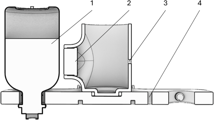
Cross-section diagram of the liquid level monitoring mechanism: (1. monitored liquid level, 2. liquid level sensor, 3–4. wiring hole).
The system employs a capacitive liquid level sensor as its core detection component. This sensor utilizes a non-contact detection principle, achieving a detection accuracy of ± 1.5 mm with a response time of 500ms, enabling high-precision real-time liquid level monitoring. The sensor features an IP67 protection grade, ensuring stable operation in medical environments. Its capability to detect through a 20 mm thick non-metallic container wall fully meets the monitoring requirements of standard infusion bottles. The NPN output interface facilitates easy integration with the control system, while its low power consumption of 5 mA guarantees long-term system stability. Detailed parameters are presented in Table 1.
The capacitive liquid level sensor has certain technical limitations, including specific requirements for the electrical conductivity of the measured liquid, potential electromagnetic interference, and specific container material constraints. However, considering that the majority of liquids used in clinical infusion therapy possess sufficient electrical conductivity, and infusion containers are typically made of non-metallic materials, these limitations do not significantly impede the sensor’s application in routine infusion monitoring. Compared to other types of liquid level sensors, the sensor used in this device not only meets basic functional requirements but also offers cost advantages and excellent adaptability, making it the optimal choice for smart infusion devices at the current stage.
From an application perspective, this sensor demonstrates significant practical value in routine infusion therapy. Firstly, the non-contact detection method completely eliminates direct contact between the sensor and the medication, adhering to the contamination-free requirements of medical equipment. The sensor’s detection accuracy and response speed satisfy the basic needs of clinical infusion monitoring. Its simple installation and maintenance facilitate easier adaptation in new equipment design and production. From a cost-effectiveness standpoint, the sensor provides an ideal price-performance ratio, which is particularly beneficial for the practical implementation of medical devices.
Relationships between core institutions
The structural design of the smart infusion device adopts a modular design concept, comprising four core mechanisms: liquid level monitoring mechanism, rotation and drug replacement mechanism, insertion and extraction mechanism, and stability calibration mechanism, as shown in Fig. 11.
The four core functional modules of the device have been spatially optimized: the liquid level monitoring mechanism utilizes high-precision sensors to real-time monitor the infusion status; the rotation and drug replacement mechanism employs a multi-position rotary platform to automatically replace medicine bottles; the insertion and extraction mechanism is responsible for precisely controlling the trajectory of the puncture needle; the stability calibration mechanism ensures the positioning of medicine bottles during the replacement process.

Core organizational structure chart.
The Component Box, serving as the control core of the device, achieves collaborative motion of the four core functional mechanisms through mechatronic design. The system’s workflow reflects the close cooperation between modules, with corresponding coordination among the four core mechanisms. Specifically, the liquid level monitoring mechanism and insertion and extraction mechanism are located on the left side of Fig. 11, with the insertion and extraction mechanism performing actions only after the liquid level sensor activates and detects the liquid; the rotation and drug replacement mechanism and stability calibration mechanism are positioned on the right side of the Fig, providing necessary stability support during rotation.When the liquid level is detected as insufficient, the liquid level detection mechanism and rotation and drug replacement mechanism interact to rotate and replace the medicine bottle on the work platform. The relationship between the stability calibration mechanism and insertion and extraction mechanism is focused on maintaining the bottle’s stability, ensuring that the puncture needle of the insertion and extraction mechanism can accurately penetrate the medicine bottle.
The relationships between the core mechanisms and their collaborative control method guarantee the reliability of coordination during the drug replacement process, thereby demonstrating the innovative value of this design in the medical device domain.
Chapter summary
This chapter provides a detailed analysis of the structural design and operational workflow of the smart infusion automatic medication replacement device. The device comprises key components such as the liquid level monitoring mechanism, rotational medication replacement mechanism, and plug-and-push mechanism. These components work in unison to achieve automated delivery and replacement of medication.
The liquid level monitoring mechanism continuously monitors the medication level, ensuring accuracy and safety during the infusion process. The rotational medication replacement mechanism, driven by a servo motor, facilitates rapid vial replacement. The plug-and-push mechanism ensures precise connection between the piercing tool and the vial. The operational workflow covers all stages from preparation and initiation to conclusion, highlighting the device’s effectiveness in reducing manual intervention and enhancing the continuity and safety of infusions. The optimization of these designs and processes provides strong support for increasing the automation of medical procedures.
link


 Vs Peers")
